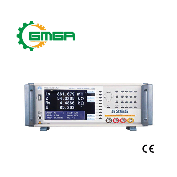
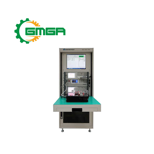
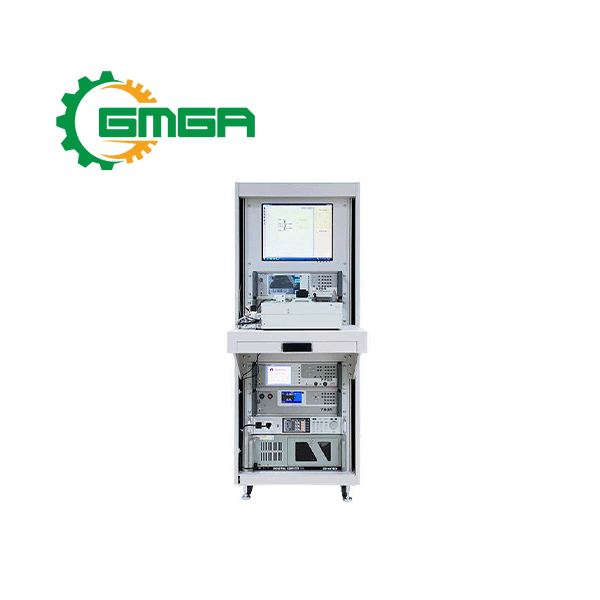
Transformer tester MICROTEST 5260 series
Price: Contact
| Model | 5260 / 5265 / 5266 / 5267 |
| Manufacturer | MICROTEST |
| Power supply | 98Vac-264Vac |
| Weight | 9 Kg |
| Size | 344 x 145 x 343 mm |
| Condition | Stocking |
| Warranty | 12 months |
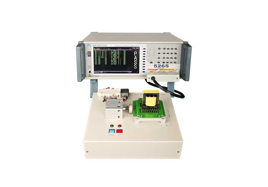
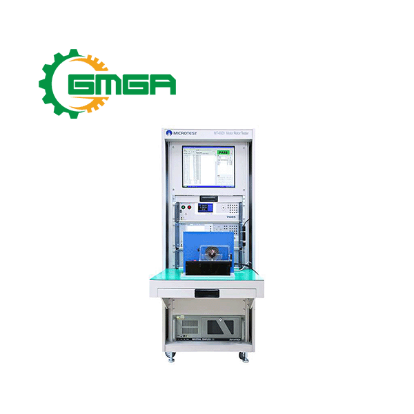
Transformer tester MICROTEST 5260 series includes inductance, leakage inductance, DC resistance, AC resistance, quality factor, capacitance, turns ratio, and checks for pin short circuits, among other items.
I. Specification of Pulse transformer tester MICROTEST 5260 series
- Transformer tester MICROTEST 5260 series is a comprehensive device that enables measurement of important parameters for transformer products.
- The measurement frequency range is from 10Hz to 200k/500k/1MHz. The tester has a built-in LCR meter measurement mode and is equipped with the F5620 pneumatic testing fixture.
- MICROTEST 5260 series provides 20 testing channels and supports 100mA DC bias testing. Customized testing fixture services are available to meet specific customer needs.
Features of MICROTEST 5260 series:
- Test Frequency: 10Hz-200kHz/500kHz/1MHz
- 20 Channels
- Support with Meter mode function, simultaneously display four parameters
- Simultaneously display four parameters
- Basic accuracy up to ±0.1%
- Open circuit/short circuit function
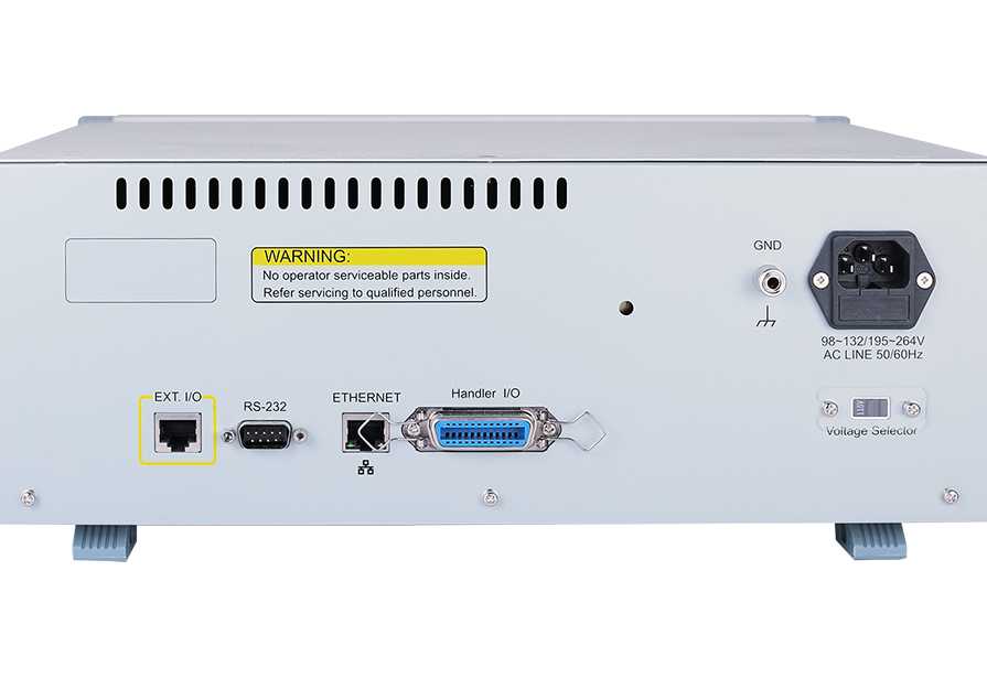
- Support RS-232, Handler, LAN, USB Host interfaces
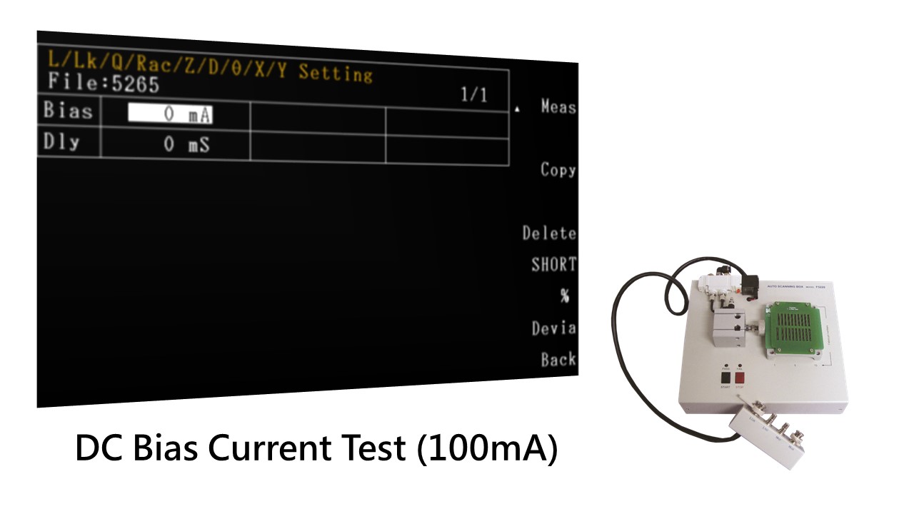
- Pneumatic fixture F5620 built-in 100mA DC Bias
- USB Host storages can storage setting files, data and capture the screen.
Applications:
- Power transformer, electronic transformer.
II. Main features of Transformer tester MICROTEST 5260 series
All-In-One low voltage electrical test:
- Inductance (L)/Leakage Inductance/Turn Ratio/Resistance (DCR)/Resistance (R)/Balance/Capacitance (C)/Short Circuit.
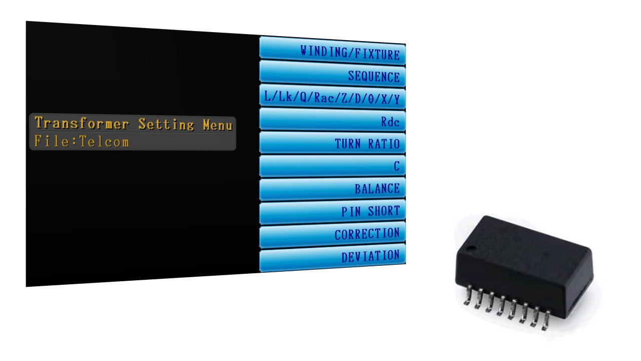
Automatic balancing bridge & 4-Wire DCR test (DC Resistance):
- Check if the winding tension is improper for Transformer.
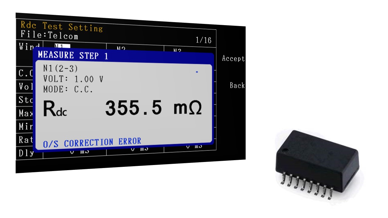
Turns ratio is an important parameter in transformer:
- Ideally, we can get the turns ratio by compare the input and output voltage.
- However, there are many parameters that might affect. So, there are some different ways to detect turns ratio.
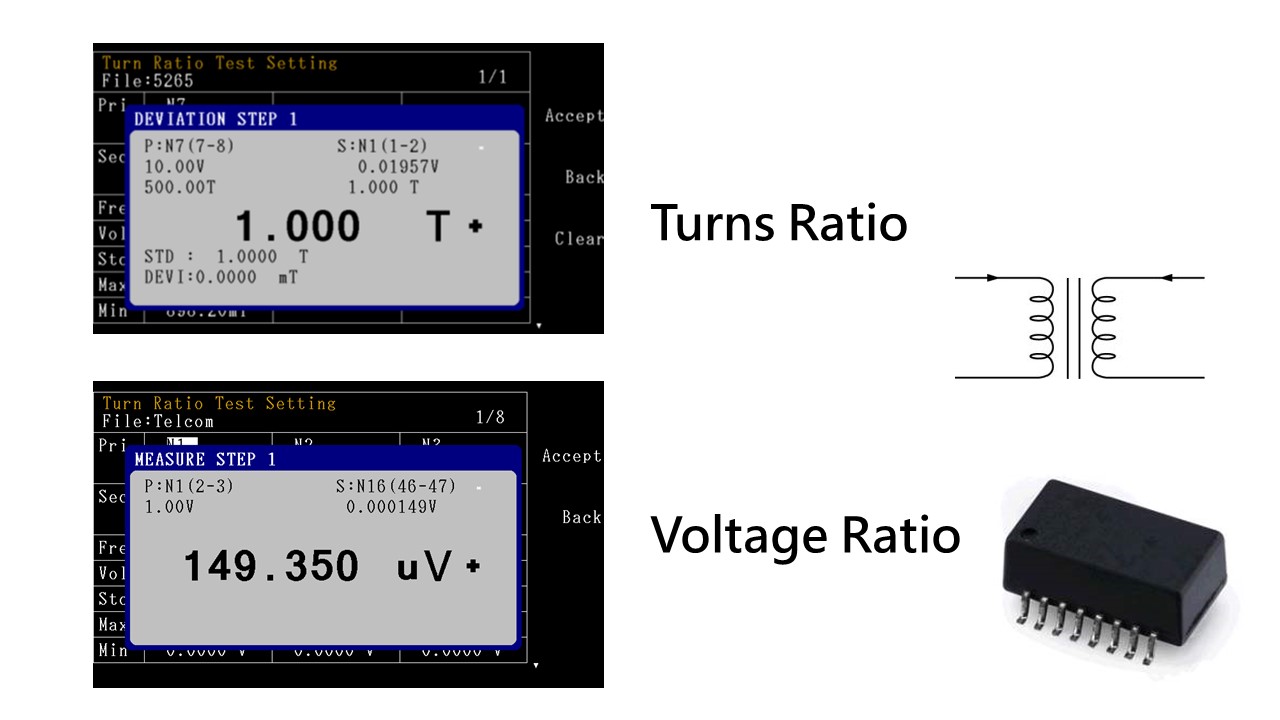
|
TR Voltage |
Put a AC voltage on primary coil, and detect the voltage on secondary coil. Compare the turns ratio and phase. |
|
TRL Inductance |
Detect the inductance on each coil, and calculate the turns ratio. The turns ratio is more accurate on transformer with bigger leakage inductance. |
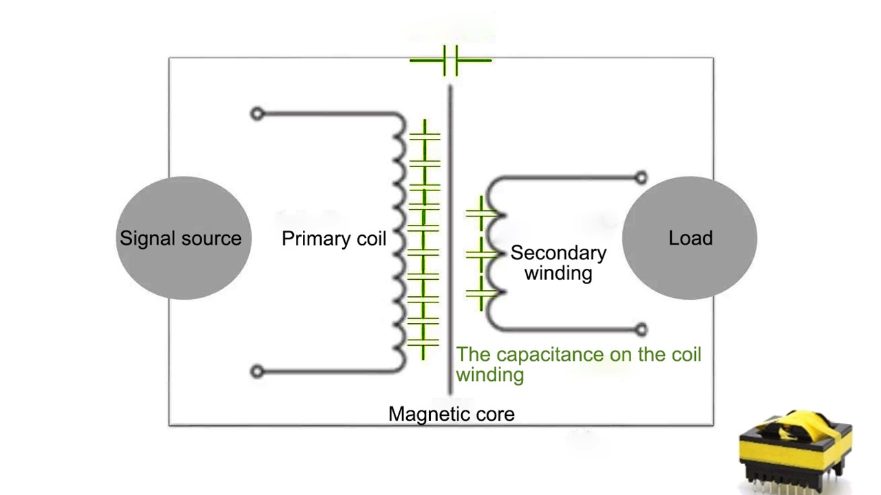
Detect capacitance to make sure the insulation between winding position and winding coil is enough:
- The winding coil on the transformer include distributed capacitance, it usually distribute between winding coil.
- Capacitance is usually represented by the capacitance by one winding to another winding in an equivalent circuit.
- Cs and Cp is an equivalent capacitance in series or parallel in equivalent circuit.
- D value is the ratio with AC resistance and capacitance, The lower the D value, is better.
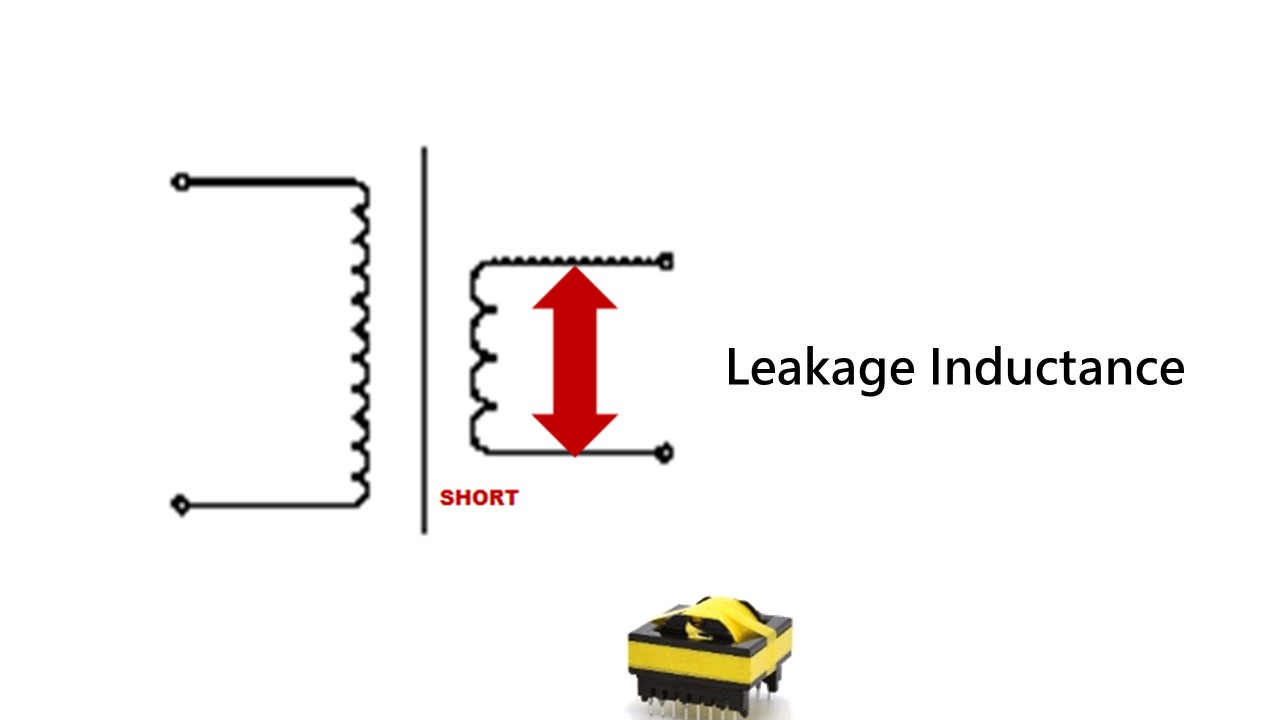
Test leakage by LCR balance bridge:
- When the instrument connect a primary coil with the transformer and the secondary coil is under open status, the test result L= Lp on primary coil + Leakage Current.
→ The leakage inside the instrument must short the secondary coil in the transformer.
A ideal secondary coil’s voltage will be 0V in short status. The voltage on both side of primary coil will be 0V. The inductance from primary coil will be the real leakage current.
Offer 100mA DC Bias Current to fulfill Netcom transformer product:
The purpose of detect DC bias is to make sure the specification of coil winding and magnetic saturation:
- The way we detect is put DC signal on AC signal. The DC signal will cause DC bias on inductance of the transformer. It might also cause magnetic saturation on transformer.
- Increase inductance by high magnetic conductivity and decrease the turns to minimize the size and raise the efficiency for inductance magnetic coil transformer. Because of the restriction of the permeability material, magnetic flux can’t be unlimited increasing. When it reach the limited, no matter increase the turns or current, the magnetic flux won’t increase. Meanwhile, it will meet the magnetic saturation especially under DC current. The AC current will not cause any change in magnetic flux. The transformer will loose the inductance feature.
The harm of magnetic saturation:
- The magnetic saturated transformer will overheat under low voltage and cause damage by time.
- It may cause explosion under high voltage.
- The inductance of primary winding will obliviously decrease on saturated transformer. Meanwhile, the power consumption on DCR and inner MOSEFT will increase rapidly. This may cause the damage on MOSEFT.
Why do we need to test 8mA for Netcom transformer:
- There is an test item that focus on open circuit inductance. Must input 8mA DC Bias, frequency 100kHz, voltage level 0.1V sine wave, and inductance>350uH.
- While the Netcom transformer is working in the LAN, positive and negative polarity rectangular pulse will create DC bias less then 8mA. This bias will make OCL decrease and cause rectangular pulse error.
- Recently, NetCom transformer not only transmit data but also DC voltage far to couple meters away(POE system). POE current is a big energy that reduce the inductance in the coil. This phenomenon will inhibit the transformer’s ability of control electromagnetic interference.
Technical data of Transformer tester MICROTEST 5260 series
Model selection:
|
Model |
5260 Series |
||
|
Test Channel |
20 |
||
|
Test Frequency |
10Hz-200kHz |
||
|
Other |
5265 |
5266 |
5267 |
|
10Hz-200kHz |
10Hz-500kHz |
10Hz-1MHz |
|
Specifications:
|
Frequency Resolution |
5 digits |
|
Basic Accuracy |
±0.1% |
|
AC Drive Level |
10mV-2Vrms |
|
DC Drive Level |
10mV-2V |
|
Output Impedance |
100Ω |
|
DC Bias Current |
100mA (F5620) |
|
Turn |
Inductance or Voltage Test Freqeuncy:50Hz-200kHz |
|
Test Mode |
Meter Mode / List Mode |
|
Parameters Measurement |
Inductance (L)、Impedance (Z)、Capacitance (C)、Resistance (R)、Conductance (G)、Susceptance (B)、Admittance (Y)、Alternating Current Resistance (ACR)、Quality Factor (Q)、θ、Direct Current Resistance (DCR)、Leakage Inductance、Turn Ratio、Balance、Short Circuit |
Parameters:
|
Parameters |
Range |
Basic Accuracy |
Speed |
|
L, LK |
0.1nH ~ 9999.99H |
0.1% |
25ms |
|
C |
0.00001pF ~ 999.99mF |
0.1% |
25ms |
|
Q,D |
0.00001 ~ 99999 |
0.0005 |
25ms |
|
Z,X,R |
0.00001Ω ~ 99.9999MΩ |
0.1% |
25ms |
|
Y |
0.01nS ~ 99.9999S |
0.1% |
25ms |
|
θ |
-180°~ +180° |
0.03° |
25ms |
|
DCR |
0.1mΩ ~ 99.999 MΩ |
0.1% |
25ms |
|
Turn |
0.1 ~ 99999.9 turns |
0.5% |
50ms |
|
Pin-Short |
12 pairs, between pin to pin |
– |
15ms |
System:
|
ESR |
Series / Parallel |
|
Calibration |
Open Circuit / Short Circuit |
|
Built-in stroage |
testing files 128 sets |
|
Operation |
Auto / Manual / Remote Trigger |
|
Power Supply |
Voltage:98Vac-132Vac or 195Vac-264Vac |
|
Power consumption |
300VA |
|
Environment |
Temperature:10℃-40℃ |
|
Dimension (W*H*D) |
344x145x343 mm (W*H*D) |
|
Weight |
9 Kg |
|
Interface |
RS-232, Handler, LAN, USB Host, EXT. I/O |
|
Display |
800*480 Color Screen, 7″ TFT |
No comments yet
SIGN UP FOR A CONSULTATION
Please fill in the form below and send your comments and questions to GMGA, we will respond to your email as soon as possible.

COMMIT
100% new product

COMMIT
100% refund if the product is of bad quality and not as promised

DELIVERY
Nationwide



Review Transformer tester MICROTEST 5260 series
There are no reviews yet.