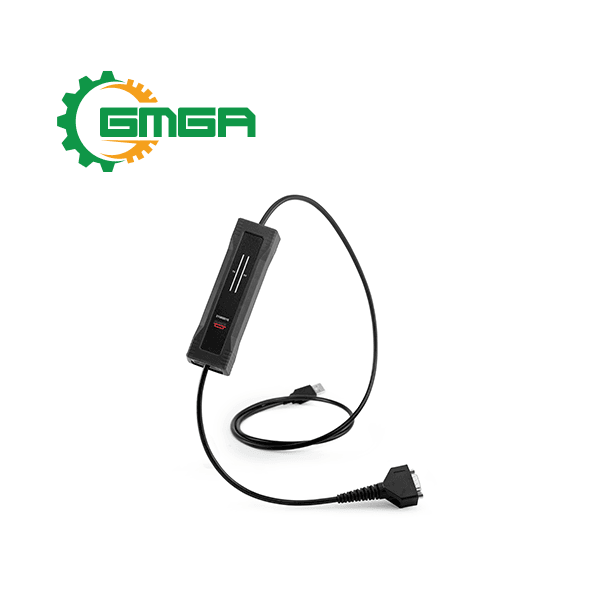
Interface CAN or CAN FD to USB single-channel robust Kvaser U100 with reinforced galvanic isolation
Price: Contact
| Model | EAN: 73-30130-01173-1 |
| Manufacturer | Kvaser |
| Power supply | Interface USB 2.0 |
| Weight | 170 g |
| Size | 38 x 128 x 26 mm |
| Condition | Stocking |
| Warranty | 24 months |
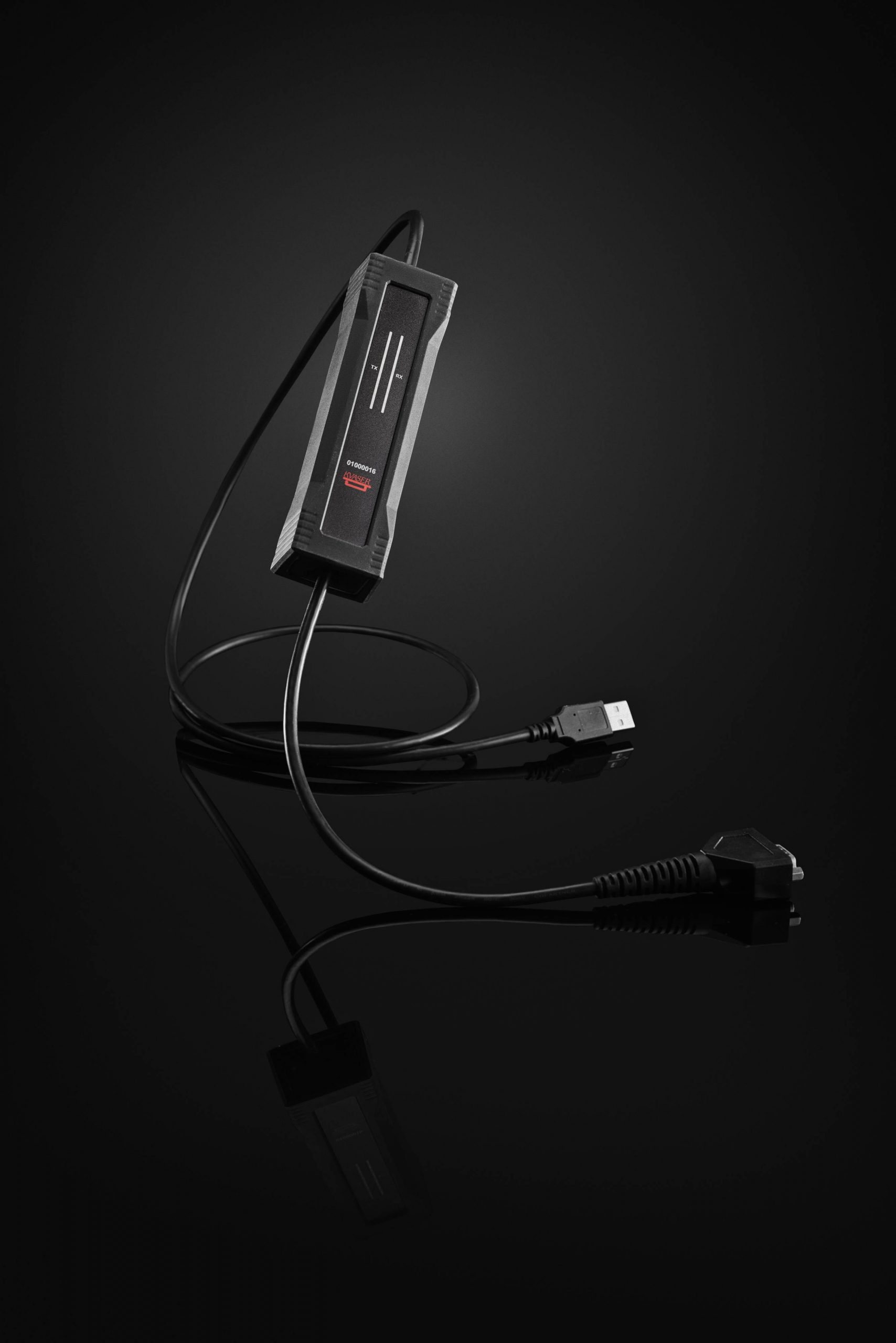
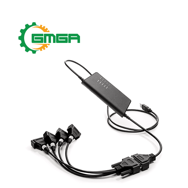
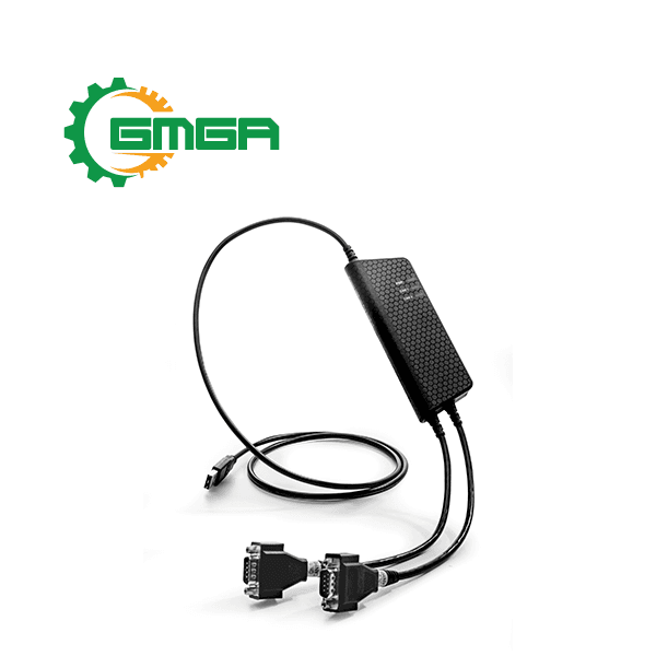
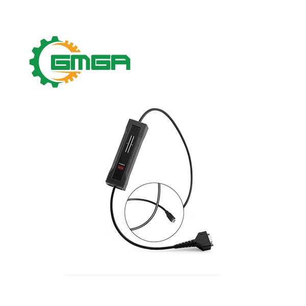
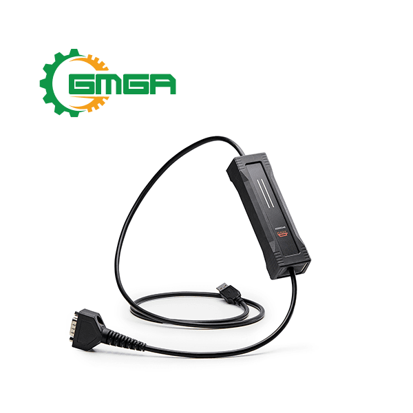
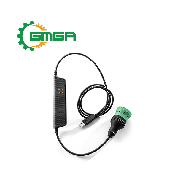
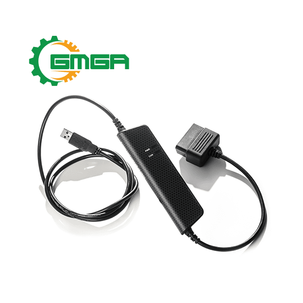
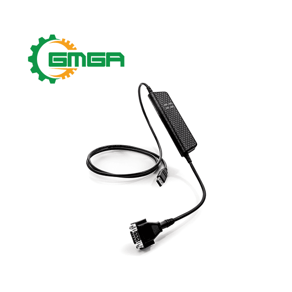
Interface CAN or CAN FD to USB Kvaser U100 (EAN: 73-30130-01173-1) is a small, yet powerful, CAN to USB interface. It provides real-time transmission and reception of standard and extended CAN messages on the bus with a high timestamp precision, and is compatible with applications that use Kvaser’s CANlib.
I. Major features of Interface CAN or CAN FD to USB Kvaser U100
- USB CAN interface.
- Powered through the USB connector.
- Supports CAN FD, up to 8 Mbit/s (with correct physical layer implementation).
- Supports both 11-bit (CAN 2.0A) and 29-bit (CAN 2.0B active) identifiers.
- Lightweight robust housing made of glass fibre reinforced polyamide overmolded with TPE.
- Intuitive LED UI.
- Reinforced galvanic isolation, design validated with 5000 VAC rms applied for 60 s.
- Industrial grade temperature range, −40 ◦C to +85 ◦C.
- 20 000 msg/s, each timestamped with a resolution of 100 μs.
- Fully compatible with applications written for other Kvaser CAN hardware with Kvaser CANlib.
- Support for SocketCAN.
- Fully compatible with J1939, CANopen, NMEA 2000® and DeviceNet.
- IP67 rated housing.
II. Sofware
- Documentation, Kvaser CANlib SDK and drivers can be downloaded for free at. www.kvaser.com/downloads.
- Kvaser CANlib SDK is a free resource that includes everything you need to develop soſtware for the Kvaser CAN interfaces. Includes full documentation and many program samples, written in C, C++, C#, Delphi, Visual Basic, Python and t programming language.
- Kvaser CAN hardware is built around the same common soſtware API. Applications developed using one device type will run without modification on other device types
III. Hardware of Interface CAN or CAN FD to USB single-channel robust Kvaser U100
Hardware installation:
- The Kvaser U100 may be inserted in any free USB socket on the host computer. You do not need to switch the power off before inserting or removing the device. For the Kvaser U100 to communicate with the host computer, a compatible version of the Kvaser driver and firmware must be installed.
- The driver is installed by running the file: kvaser_drivers_setup.exe. For instructions on how to update the firmware. The latest version of the driver and firmware can be downloaded from: www.kvaser.com/download.
- The firmware is downloaded and installed directly on the Kvaser U100 and the driver is installed on the host computer. After the driver has been installed on the host computer, the firmware may then be downloaded and installed on the Kvaser U100.
USB connection:
- The USB connector for the Kvaser U100 is a standard USB type “A” connector .
- Connect the device to your computer using any high quality USB 2.0 certified cable. The maximum total USB cable length is 5 m (∼ 16 ft).
CAN connection:
- The Kvaser U100 has one CAN channel.
- The CAN connector for the Kvaser U100 is the 9-pin D-SUB connector.
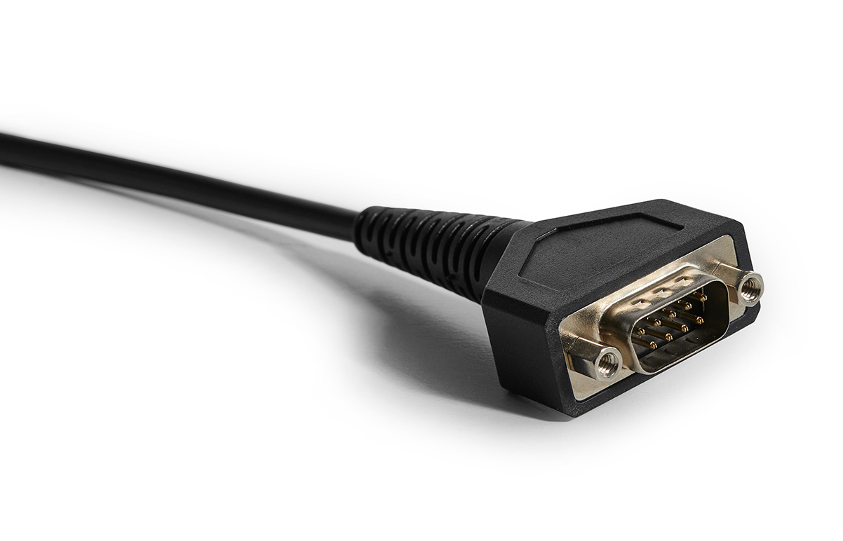
|
D-SUB pin |
Function |
|
1 |
Not connected |
|
2 |
CAN_L |
|
3 |
GND |
|
4 |
Not connected |
|
5 |
Shield |
|
6 |
Not connected |
|
7 |
CAN_H |
|
8 |
Not connected |
|
9 |
Not connected |
CAN bus termination:
- Every CAN bus must be terminated with a 120 Ohm resistor at each end of the bus. The galvanically-reinforced single-channel CAN/CAN FD to USB interface Kvaser U100 does not contain any CAN bus termination, because their inclusion could cause severe disturbance in a system which is already correctly terminated.
- For laboratory or testing use, the exact value of the termination resistors is not always critical. Sometimes a single terminator is sufficient. For production, proper termination is essential. If you see error frames on the bus, you should check the termination.
Power supply:
- The Kvaser U100 is powered through the USB connector. Make sure the USB power source can supply enough current (500 mA). If using a USB hub, choose an externally powered one to be safe.
LED Indicators:
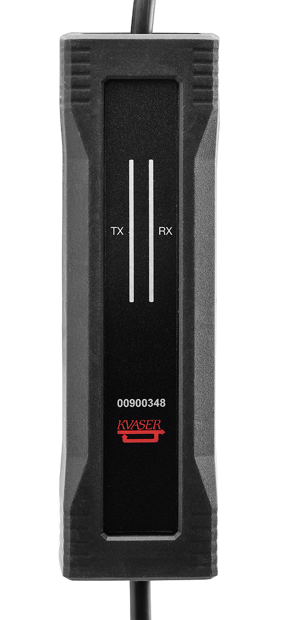
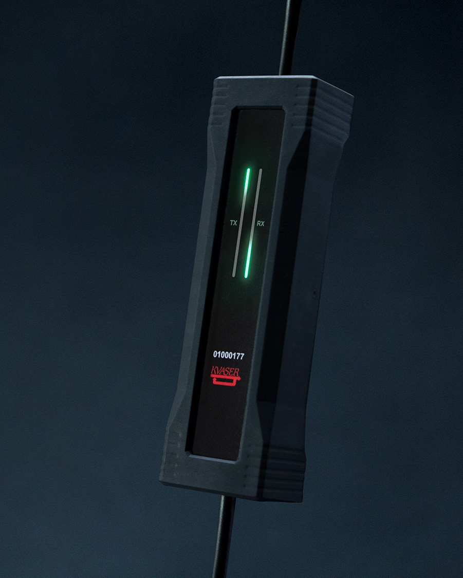
- A Kvaser U100 device has two traffic LED bars where part of each LED bar is also used as a status area. The TX LED Bar has a status area towards the USB end of the bar, and the RX LED bar has a status area towards the CAN end of the bar.
- Different colors are used for different types of information and different blink patterns define the current state.
|
Color |
Information type |
|
Yellow |
Traffic |
|
Green |
Status |
|
Red |
Error |
|
White |
Alert |
|
Blue |
System |
|
State |
Definition |
|
Off |
The indicator is off and no light is emitted. |
|
Slow Blink |
The indicator is repeatedly turned on and off. The on and off phases are equal in time. |
|
Fast Blink |
The indicator is repeatedly turned on and off but with a higher frequency than Slow Blink. The on and off times are still equal. |
|
On |
The indicator is constantly emitting light. |
|
Dynamic |
The indicator is moving and/or increasing/decreasing in size. |
Interface mode:
- The device is in interface mode when connected to a computer via USB. If the status area is presenting a steady white light, the device is in interface mode, working correctly and ready to be used. When connected to a computer for the first time, the status area will Fast Blink with blue light until the Kvaser Drivers are installed and the device has automatically received a USB configuration. The status area will change from white to green when going bus on.
|
Description |
Status area |
LED bar |
|
Power is on |
On (White) |
- |
|
Waiting for USB configuration |
Fast Blink (Blue) |
- |
|
CAN channel is bus on |
On (Green) |
- |
|
CAN channel traffic |
On (Yellow) |
Dynamic (Yellow) |
|
Error frame |
- |
Dynamic (Red) |
|
CAN channel is error passive |
Fast Blink (Red) |
- |
|
CAN overrun |
On (Red) |
- |
|
Firmware update |
Slow Blink (Blue) |
- |
|
Locate hardware |
Slow Blink (White) |
Slow Blink (White) |
- The Kvaser U100 has one TX LED Bar and one RX LED Bar. Each LED Bar has a status area, the TX LED Bar has a status area towards the USB end of the bar, and the RX LED bar has a status area towards the CAN end of the bar.
- The TX LED bar lit area grows from the USB end of the LED bar towards the CAN end of the bar as CAN TX traffic is increased. Likewise, the RX LED bar lit area grows from the CAN end of the LED bar towards the USB end of the bar as the message rate of the received traffic is increased.
- The combined area lit by the TX LED bar and the RX LED bar is proportional to the current bus load.
Technical data of Interface CAN or CAN FD to USB Kvaser U100 with reinforced galvanic isolation
|
CAN Channels |
1 |
|
CAN Connector |
9-pin D-SUB |
|
CAN Transceivers |
ADM3055E (Compliant with ISO 11898-2) |
|
CAN Controller |
Built into the processor. |
|
Galvanic isolation |
Yes, reinforced. Design validated with 5000 VAC rms applied for 60 s. |
|
CAN Bit Rate |
10 kbit/s to 1 Mbit/s |
|
CAN FD Bit Rate |
Up to 8 Mbit/s (with correct physical layer implementation). |
|
Time stamp resolution |
100 μs |
|
Max message rate |
20 000 msg/s per channel |
|
Error Frame Detection |
Yes |
|
Error Frame Generation |
No |
|
Silent mode |
No |
|
Kvaser MagiSync |
No |
|
Kvaser t programming |
No |
|
Kvaser CANtegrity |
No |
|
Host interface |
USB 2.0, standard USB type “A” connector |
|
Host OS |
Windows (7 or later), Linux |
|
Power consumption |
Typical 250 mA |
|
Dimensions |
38 x 128 x 26 mm for body |
|
Cable length |
USB 1.0 m, CAN 0.3 m |
|
Weight |
170 g including connectors |
|
Operating temperature |
−40 ◦C to +85 ◦C |
|
Storage temperature |
−40 ◦C to +85 ◦C |
|
Relative humidity |
0 % to 85 % (non-condensing) |
|
IP Rating Housing |
IP67 |
|
IP Rating CAN connector |
IP40 Mated |
|
IP Rating USB connector |
IP40 Mated |
No comments yet
SIGN UP FOR A CONSULTATION
Please fill in the form below and send your comments and questions to GMGA, we will respond to your email as soon as possible.

COMMIT
100% new product

COMMIT
100% refund if the product is of bad quality and not as promised

DELIVERY
Nationwide




Review Interface CAN or CAN FD to USB single-channel robust Kvaser U100 with reinforced galvanic isolation
There are no reviews yet.